The new SoftiMAX STXM: CHIARA
The main branch at SoftiMAX provides an energy range of 275 eV – 2500 eV, and polarisation modes linear horizontal/vertical, inclined, and circular.
A new STXM system will go into commissioning in the Fall 2025 period. The end-station will initially be open for general users for the following methods only:
| Method | Detectors | Sample environment |
|---|---|---|
| STXM with a focal spot size of 30 nm and upwards | PMT (full range) | Magnetic field (415 mT in-plane and out-of plane)* Sample heater (Norcada), up to 1100°C |
| Ptychography | Tuscen Dhyana 95 (275 – 900 eV), direct detection; back-illuminated sCMOS, up to 24 fps; 2048 x 2048 pixels, 22.528 × 22.528 mm; 11 µm pixel size. EIGER LGAD (500 – 2500 eV, 512×512, 75 μm pixel size) Andor Zyla 5.5 (500 – 2500 eV), with FOP (3 µm channel diameter) and P43 scintillator (5 µm thickness); front-illuminated sCMOS, up to 100 fps; 2560 x 2160 pixels, 16.6 x 14.0 mm | Magnetic field (415 mT in-plane and out-of plane)* Sample heater (Norcada), up to 1100°C |
*The magnet system will restrict the energy range.
Please contact beamline staff to discuss the details of the experiment, in particular if sample environment is required.
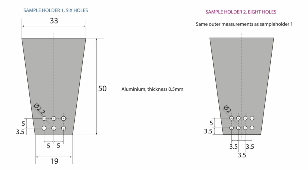
Sample mounting (SoftiMAX STXM)
The SoftiMAX STXM uses metal plate sample holders in 6 and 8 hole variants (available at the beamline). The sample holders support TEM grids and silicon nitride membranes with an outer dimension from 3 x 3 mm2 to 5 x 5 mm2. The membrane thickness should be 50–100 nm, depending on X-ray energy. The membrane sizes should be from 0.5 x 0.5 mm2 up to 1.5 x 1.5 mm2. Grids and membranes can be stuck to the holders by nailpolish or sticky tape (available at the beamline).
The SoftiMAX-CXI open port
The second branch at SoftiMAX is offered as an open port for external user end-stations:
| Energy range | 275 eV – 2100 eV |
| Beam size (focus) | 10 μm (H) × 15 μm (V)* |
| Beam height (focus) | 1404.8 mm |
| Beam inclination | +2 deg |
*beam size in focus is energy dependent.
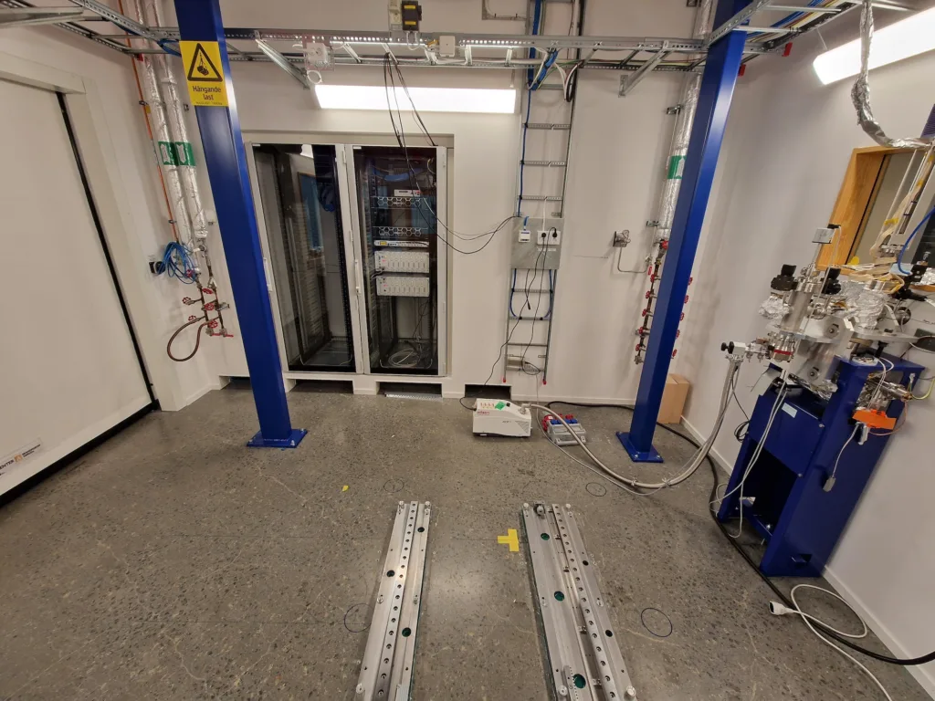
SoftiMAX-CXI open port area. A drawing with dimensions is available upon request.
The CXI end-station
The new Coherent X-ray Imaging end-station will be offered in the Spring 2026 call for user operation for the first time. This end-station can be moved into the open port location at SoftiMAX, and use the beam described above. It features a Teledyne PI-MTE3 4096B CCD, with a pixel size of 15 μm and sensor size of 60 mm x 60 mm. The detector can be rotated around the sample by up to 120 degrees in the horizontal plane, and the distance to the sample can be increased to at least 2 meters.
The end-station is suitable for methods such as Coherent Diffractive Imaging (CDI), Fourier Transform Holography (FTH), and X-ray Photon Correlation Spectroscopy (XPCS). Due to the flexible detector geometry, measurements in reflection are also possible.
The sample holders used in the STXM can also be used at CXI.
STXM mode
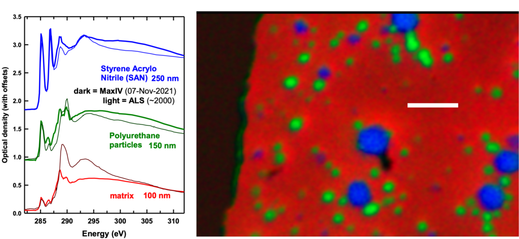
The STXM mode uses the PMT detector, and is limited in resolution by the spot size of the illumination. At 300 eV, the smallest spot size is about 30 nm, between 700 eV and 1600 eV, the smallest spot size is about 22 nm, and above 1600 eV the smallest spot size is about 60 nm. STXM can provide absorption contrast. The energy resolution is better than 50 meV in the commissioned energy range.
Ptychography mode
The Ptychography mode uses a pixel detector; Currently the Andor Zyla is available. The sample can be moved out of focus to adjust the illumination spot size and the overlap. The detector distance can also be varied. The data can be analyzed on the MAX IV computing cluster using the Ptypy-package. Ptychography can provide both absorption and phase contrast.
The following detectors are available:
| Detector type | Model and specification |
|---|---|
| Photodiode | Opto Diode Corp AXUV20HS1 |
| PMT | Hamamatsu H3164-10, with P43 scintillator |
| 2D detector | Andor Zyla 5.5, with FOP (3 µm channel diameter) and P43 scintillator (5 µm thickness); front-illuminated sCMOS, up to 100 fps; 2560 x 2160 pixels, 16.6 x 14.0 mm; The detector distance can be varied between 33 mm and about 150 mm. |
| 2D detector | Tuscen Dhyana 95, direct detection; back-illuminated sCMOS, up to 24 fps; 2048 x 2048 pixels, 22.528 × 22.528 mm; 11 µm pixel size. Under commissioning |
| SDD | Amptek X123 Fast SDD,70 mm2; C2 window (Si3N4). Under commissioning |